Applications
Optimise, simulate and innovate with MORe.
Process insights with Toolyzer & MORe
What
The cutting process introduces complex forces that, together with machine dynamics, interact to influence the surface quality.
How
Combine the following tools to simulate the interaction between the cutting process and the machine:
Toolyzer: Simulates cutting tools and processes in full detail, from 5-axis milling to special gear cutting processes like skiving and hobbing. Tool engagement conditions such as chip thickness or effective angles, forces, and resulting workpiece quality become transparent right from the start.
MORe: Delivers the accurate dynamic model of the machine at any machining position and shows the vibrations of the fully coupled system whether stable or chattering.
Why
Predict stability and surface quality before making a single chip.
Cylindricity error of a coordinate grinding machine
What
In coordinate grinding, achieving high roundness and cylindricity accuracy is essential for precise surface quality and functional performance.
How
By simulating specific processes such as planetary or chopping grinding, position-dependent TCP deviations can be evaluated to accurately calculate and optimise the cylindricity.
Why
Understanding and quantifying machine performance forms the foundation for systematic performance improvement and cost reduction.
Positioning accuracy of a wafer stage
What
Wafer inspection in semiconductor production is a crucial quality assurance step, but it is also subject to high efficiency demands and strict cycle-time requirements. The positioning stages must operate with high dynamic performance while maintaining sub-micron to nanometer accuracy to ensure precise alignment and measurement.
How
Transient simulation of the move and settle behaviour within seconds. Nonlinear effects such as friction and cable masses are taken into account, and the settling time is systematically evaluated to verify whether the required cycle time can be achieved.
Why
Quantifying quality criteria such as settling time is essential to verify customer requirements and provides a clear basis for optimising system design and performance.
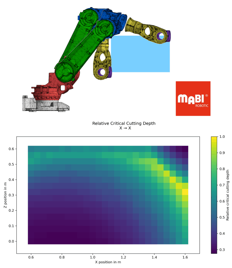
Critical cutting depth of a CNC milling robot
What
Cutting processes with robots are particularly challenging due to the flexibility and dynamic behaviour of the system. It is essential to understand position-dependent process stability, i.e. the critical cutting depth at which the process becomes unstable.
How
By performing frequency response analyses with position variation across the working area, process stability can be evaluated for the relevant cutting parameters and operating conditions.
Why
Understanding the dynamic behaviour of the robot enables optimisation of cutting parameters and robot trajectories, leading to higher process stability and improved machining quality. Furthermore, machine setup is simplified, as the previous trial-and-error search for suitable poses is no longer required, since these conditions can now be evaluated through simulation.
Worst-case positioning of a gantry portal
What
Positioning the axes is a common application in automated systems. The key factors here are overshoot and settling time at the point of interest, which depend on the selected dynamic limits and the positioning length.
How
Transient simulation of the move and settle behaviour within milliseconds with the Linear Periodic Response Solver. Systematic evaluation of overshoot and settling time through parameter studies such as variation of positioning length. Evaluation of the worst-case and best-case scenarios.
Why
Knowing the positioning behaviour helps to reduce risks during development and optimise your design. In addition, customer specifications can be checked in advance.
Geometric accuracy of linear axes
What
Ensuring straight-line motion in machine tool components is crucial for producing precise and flat workpieces. This accuracy affects the positional accuracy of any point on the workpiece, making it essential for high-precision production.
How
Evaluate the positioning, straightness, and tilt for straight-line motion according to the definitions in the ISO 230-1 standard, taking into account influences such as gravity, rail errors, or thermal effects.
Why
Knowing geometric errors of the machine tool helps to understand where improvements are necessary and where tolerances could be relaxed in order to save costs.
Contour error evaluation
What
Deviations from the desired setpoints during machining cause workpiece errors.
How
Solve transient simulations of your setpoints and evaluate the dynamic contour error of the mechatronic system at the TCP. Consider and compare various influences like:
- structural dynamics
- friction
- feedforward control
- controller parametrisation
- setpoint variation
- position dependency
Why
Knowing the dynamic contour error helps to assess the performance of the machine, find limitations and achieve the best possible performance.
Dynamic tracking error evaluation
What
The dynamic tracking error describes the deviation of the actual trajectory to the set point, disregarding the deviation caused by a lag. Consequently, it’s the only part of the tracking error that leads to contour errors if axes are synchronised.
How
With just one frequency response analysis in the closed control loop, you can evaluate the dynamic tracking error of the mechatronic system. The error takes into account the dynamic limits of your machine and can be analysed on the encoder and the TCP.
Why
Knowing the dynamic tracking error in the frequency domain means that you know the worst-case error at the TCP for all possible setpoints. By animating the vibration shape, you can identify bottlenecks and optimise the performance of your machine, overcoming limitations and adding improvements in the right spots.
Thermal drift
What
How
Evaluate the TCP displacement over time (thermal drift) by considering various thermal influences, including but not limited to:
- changing environment temperature
- switching cutting fluid on/off
- motor power losses
- cooling (e.g. motor, structure, spindle)
- local heat sources and sinks
Why
Understand thermal influences and accuracy and use this knowledge to improve thermal stability.
Switching cutting fluid on/off
What
How
Solve seamless transient simulations with changing heat transfer coefficients. Evaluate the temperature and displacement at probes (e.g. TCP).
Why
Understand thermal influences and accuracy and use this knowledge to improve thermal stability.
Spindle imbalance
What
Spindle vibrations caused by imbalance are a well-known problem in many production machines. The resulting TCP deviation depends on the dynamic properties of the machine and the spindle speed.
How
Evaluate the frequency response of your machine by considering a complete spindle run-up and imbalance in different directions. Analyse the TCP displacement and rotation as well as the animation of the vibration as a function of the spindle speed.
Why
Understanding the influence of imbalances on the dynamic behaviour of your machine helps to optimise your design, define requirements on balancing, and increase performance.
Varying machining positions
What
Large linear or rotating movements during machining can change the thermal boundary and coupling conditions, such as the location of heat transfer from linear guide carriages to rail. This leads to a change in the thermomechanical behaviour and can thus lead to displacements at the TCP.
How
Efficiently solve transient thermal and thermomechanical simulations with position variations. Evaluate the displacement at the TCP for different machining positions.
Why
Understanding the influence of position variations on thermomechanical behaviour is crucial to achieve thermal robustness within the entire workspace.
Process stability
What
During the cutting process, machines can experience chatter, resulting in reduced accuracy and increased forces on the spindle and tool. Ensuring a stable cutting process is critical to maintaining precision and preventing damage or excessive wear.
How
By efficiently solving a frequency response analysis and evaluating process stability across the relevant cutting parameters and spindle speed range, you can estimate the critical cutting depth and animate the chatter frequency. This helps visualise potential issues before they arise.
Why
Knowing the critical cutting depth is key to minimising risks during product development and meeting customer requirements. Moreover, understanding the mode shape of the chatter frequency offers valuable insights for systematically optimising machine design and improving performance.
Want to see more?
These applications are just a selection of what is possible using MORe.