Belt drive
Belt drive link properties implement a toothed belt drive. Only the linear elastic behaviour is modelled, non-linearities are neglected. The simplifications are:
- the belt is always considered prestressed (both strands are contributing to the stiffness)
- the prestress force is not modelled and has to be added as load in an analysis if desired
- irregular transmission due to the teeth is not modelled
- local deformation of the pulleys is not modelled
Definition
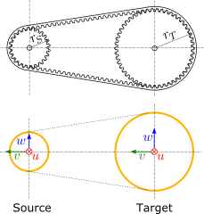
Source and target interfaces should be chosen as shown in following figure:
Source interface
| Type |
Stationary interface (6dof) |
| Topologies |
Peripheral face of the source pulley |
| Location |
Center of the source pulley |
| u direction |
Axial, along the axis of rotation of the source pulley |
| v direction |
Pointing towards the center of the target pulley |
| w direction |
Resulting direction |
Target interface
| Type |
Stationary interface (6dof) |
| Topologies |
Peripheral face of the target pulley |
| Location |
Center of the target pulley |
| u direction |
Axial, along the axis of rotation of the target pulley |
| v direction |
Aligned with the v-direction of the source interface |
| w direction |
Parallel to the w-direction of the source interface |
Recommended link settings
| Use ground for source |
unchecked |
| Location master |
none |
| Orientation master |
either source or target |
Parameters
| Parameter |
Unit |
Symbol |
Description |
|---|
| Source gear radius |
m |
\(r_S\) |
Radius of the pitch line of the source pulley |
| Target gear radius |
m |
\(r_T\) |
Radius of the pitch line of the target pulley |
| Belt stiffness |
N/m |
\(k\) |
Stiffness of one strand of the belt including tooth compliance |
| Belt damping |
Ns/m |
\(d\) |
Damping coefficient of one strand of the belt |
The stiffness of the belt can be calculated using the specific stiffness \(c_{st}\), the width of the belt \(b\), and the free lenght of a strand \(l_{1}\) according to \(k = c_{st} \, b / l_1\).