Gearmotor
Introduced in MORe v4.2
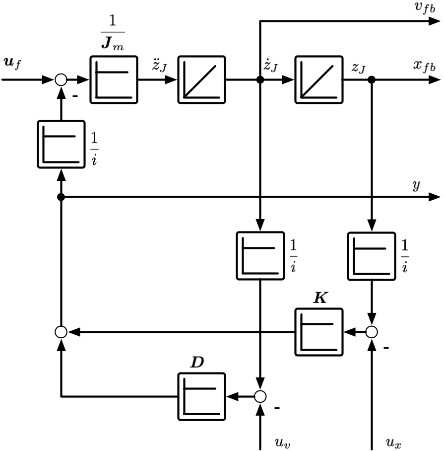
Represents a geared motor. Models rotor and gear inertia including gear reduction.
Block diagram
Signal |
Description |
|---|---|
\(u_f\) |
Filter output |
\(u_v\) |
Coupling link velocity |
\(u_x\) |
Coupling link position |
\(v_{fb}\) |
Motor velocity. Can be used as feedback in architecture. |
\(x_{fb}\) |
Motor position. Can be used as feedback in architecture. |
\(y\) |
Motor output. Force acting on coupling link. |
Parameter
Coupling
Link selection to represent the motor. The controller output (force/torque) will be applied to the selected link.
