Architecture
Introduced in MORe v3.1
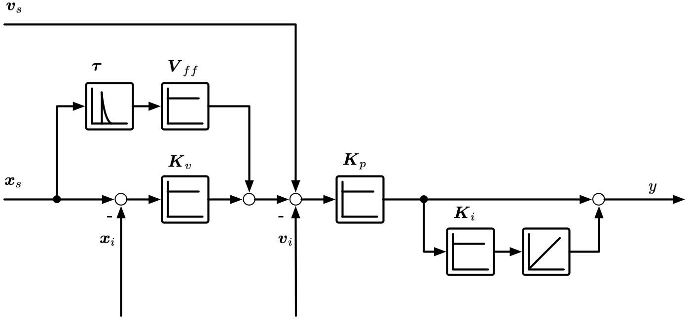
Represents a cascaded loop with a velocity loop and a position loop.
Block diagram
Signal |
Description |
|---|---|
\(x_{s1}\) |
Setpoint position used with the “Position command value” load (scaled to correspond to the position encoder) |
\(x_{sk}\) |
Setpoint position used with the “Position command value with setpoint scaling” load |
\(x_{i}\) |
Actual/indicated position (feedback from position encoder) |
\(v_{i}\) |
Actual/indicated velocity (feedback from velocity encoder) |
\(v_{s}\) |
Setpoint velocity (scaled to correspond to the velocity encoder) |
\(y\) |
Total (unfiltered) command force/torque |
Parameter |
Units linear |
Units rotary |
Description |
|---|---|---|---|
\(K_v\) |
\(1/s\) |
\(1/s\) |
Proportional gain of the position controller |
\(K_p\) |
\(Ns/m\) |
\(Nms/rad\) |
Proportional gain of the velocity controller |
\(K_i\) |
\(1/s\) |
\(1/s\) |
Integral gain, \(K_i=1/T_{ni}\). Use \(T_{ni}=0\) to disable. |
\(K_{vff}\) |
\(-\) |
\(-\) |
Velocity feed-forward gain (use 0-1) |
\(K_{aff}\) |
\(kg\) |
\(kgm^2\) |
Acceleration feed-forward gain. Use the expected inertia for the full feedforward correction, with the inertia corresponding to acceleration on the position encoder (not on the velocity encoder) |
\(\tau\) |
\(s\) |
\(s\) |
Feedforward filter time constant (see below for details) |
Loop closure settings
Velocity loop closed
Disable to open the velocity feedback loop.
Position loop closed
Disable to open the position feedback loop.
Measurement scaling parameters
Setpoint to position scaling
The scaling value \(K_{pos}\) is used to scale the position setpoints for the controller. This makes it possible to use linear position setpoints in data tables for controllers with indirect feedback (only motor position). Select the “Position command value with setpoint scaling” controller command load for transient jobs to activate the \(x_{sk}\) input and use the \(K_{pos}\) value set in the controller. Selecting the usual “Position command value” controller command load will use the unscaled \(x_{s1}\) input.
Example:
Ballscrew drive with indirect feedback. Set \(K_{pos}=2 \pi / hs\) (spindle pitch \(=hs\)).
Position to velocity encoder ratio
For controllers with two different feedback sources (e.g. linear scale for position feedback, rotary encoder for velocity feedback), the linear velocity setpoint generated by the position loop needs to be scaled to rotary velocity setpoint for the velocity loop using \(K_{vel}\) in the controller. The default value is 1.
Example:
Ballscrew drive with direct (linear scale) feedback. Set \(K_{vel}=2 \pi / hs\) (spindle pitch \(=hs\)).
Feedback control parameters
The full description of the feedback control parameters is given in the block diagram & table above.
Feedforward control parameters
When using either velocity or acceleration feedforward, first order highpass filters are used to approximate derivatives to generate the feedforward signals. The maximum usable position setpoint angular frequency \(\omega\) is defined by the time constant \(\tau\). The excitation \(\omega\) must satisfy \(\omega \tau << 1\). The standard setting has \(\tau=1μs\), and is therefore valid for \(\omega << 1Mrad/s\). When feedforward is used, transient calculation times can sometimes be reduced by increasing \(\tau\), however the condition \(\omega \tau << 1\) must be maintained.
Feedback devices
Feedback source
Select “Link” to use a link output as feedback (direct feedback). If the controller contains a motor, an output of the motor can be selected (indirect feedback).
Link selection
Only visible if selected entity is “Link”. Select a link to be used as feedback.